
Currently Empty: $0.00

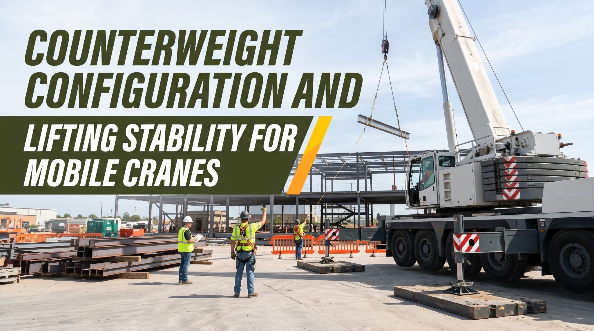
Counterweight Configuration and Lifting Stability for Mobile Cranes
A mobile crane can lift a steel beam into place and then fail on the next pick, even though nothing about the machine has changed. The beam was the same weight, but the boom reached a few feet farther, an outrigger pad sat on softer ground, or a gust caught the load as it cleared the building line. Crane stability is never decided by one component. It comes from the balance between the load, the crane’s structure, its counterweight, its boom configuration, and the ground beneath it.
Counterweights are among the most visible parts of that balance. They are the heavy steel or cast slabs at the rear of the upper structure that resist the overturning force created by a suspended load. Without the correct counterweight, many mobile cranes could not achieve their rated lifting performance. Counterweights, however, do not make a crane safe under every condition. They work only within the specific configurations the manufacturer has engineered and tested, and only when the rest of the crane system is set up correctly.
That distinction matters on every jobsite. A crane carrying the right counterweight can still tip if the outriggers are short-rigged without the matching chart, if the ground gives way under a pad, or if the load radius drifts beyond the planned limit. A crane carrying the wrong counterweight, or more counterweight than the configuration allows, can become unstable in ways operators may not expect, including backward tipping when the boom is raised with no load on the hook.
The Role of a Crane Counterweight
Every suspended load tries to pull the crane forward and over its tipping axis. A counterweight adds mass behind the crane’s center of rotation to resist that pull. The heavier the load and the farther it sits from the crane, the more resisting force the crane needs to stay stable.
Manufacturers design counterweight amounts and positions around specific crane configurations. A given counterweight package is matched to particular boom lengths, outrigger settings, and load chart tables. Many all-terrain and crawler cranes use modular counterweight slabs that can be added or removed, which allows the crane to travel within road weight limits and then be configured for the planned lift on site. Each permitted arrangement corresponds to its own set of rated capacities.
Counterweights never act alone. They work as part of the complete crane system, which includes the boom, the carrier or crawler base, the slewing structure, the outriggers, and the supporting ground. If any of those elements is set up incorrectly or fails, the counterweight cannot restore stability.
Counterweight also cannot compensate for exceeding the crane’s rated capacity. Some capacities on a load chart are limited by structural strength rather than stability, meaning the boom or another component would fail before the crane tipped. Adding mass at the rear does nothing to increase structural limits. Operating outside the manufacturer’s approved setup removes the engineering basis for every number on the chart.
Key takeaway: A counterweight balances the overturning effect of a suspended load within manufacturer-engineered configurations, but it works only as part of the complete crane system and cannot compensate for exceeding rated capacity or using an unapproved setup.
Planning and Verifying a Safe Lift
A safe lift is planned before the crane arrives and verified before the load leaves the ground. Every element of the crane configuration must match the load chart, and every person involved must understand the plan. Confirm these five points before each lift.
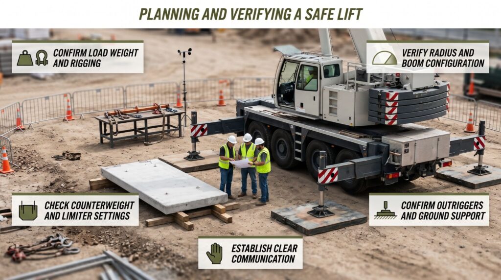
- Load Weight and Rigging: Confirm the actual load weight, then add the hook block, slings, shackles, spreader bars, and other rigging that count against rated capacity.
- Radius and Boom Configuration: Verify the working radius at pickup, during travel, and at placement, along with boom length, jib, and boom angle.
- Counterweight and Limiter Settings: Check that the installed counterweight matches the approved configuration and that the rated capacity limiter is programmed to the same setup.
- Outriggers and Ground Support: Confirm outrigger extension, leveling, mat placement, and ground bearing capacity all match the lift plan and load chart.
- Communication and Signal Person: Establish clear communication, assign a qualified signal person where required, and secure the swing and load paths from unauthorized entry.
Key takeaway: Verify load weight and rigging, radius and boom configuration, counterweight and limiter settings, outrigger and ground support, and communication before every lift, and never estimate capacity from counterweight size or general rules.
Load Moment and Stability
Crane stability depends on more than load weight. It depends on load moment, which is the load’s weight multiplied by its horizontal distance from the crane’s tipping axis. That distance is closely tied to the working radius, measured from the center of rotation to the center of the hook or load.
As radius increases, load moment increases, even when the load weight stays exactly the same. A load that the crane handles comfortably close in can become unsafe when the boom is lowered or extended to reach farther out. That is why load charts show capacity falling steadily as radius grows. Doubling the radius roughly doubles the overturning moment, and capacity at long radius can be a small fraction of the crane’s maximum rating.
Counterweight configuration is one factor in how much load moment the crane can resist. Boom length, boom angle, outrigger extension, slewing position, and whether the crane is working over the front, side, or rear all influence the result. Many cranes have different capacities depending on the working area, because the tipping axis changes as the upper structure rotates relative to the outriggers or tracks.
Operators must use the correct load chart for the exact crane setup. This means matching the chart to the installed counterweight, boom length, any jib or extension, outrigger position, working area, and operating conditions. Hydraulic flow must also be checked against the crane’s requirements because it affects the operation of hydraulic functions, including lifting, boom movement, and extension systems, depending on the crane design. Most modern cranes also use a rated capacity limiter or load moment indicator, which must be programmed to match the actual configuration. An indicator set for full counterweight while the crane carries a reduced package can provide dangerously misleading information.
Key takeaway: Load moment rises with working radius even when load weight stays constant, so always use the load chart and capacity limiter settings that match the crane’s exact counterweight, boom, outrigger, and working-area configuration.
Counterweight Position and Configuration
Mobile cranes may use different counterweight amounts or arrangements depending on the model, the lift plan, and transport requirements. Some cranes allow partial counterweight packages for lighter work or restricted sites. Others offer variable counterweight positions or additional superlift or ballast systems for heavy lifts. The manufacturer specifies every permitted configuration, along with installation procedures, required pin and locking arrangements, and any operating restrictions tied to each setup.
Changing the counterweight arrangement without authorization alters the crane’s rated capacity and stability characteristics. Removing counterweight reduces resistance to forward tipping. Adding counterweight beyond an approved configuration can create a different hazard: backward instability. When the boom is raised to a high angle with little or no load on the hook, the combined center of gravity shifts rearward. An unapproved increase in counterweight can push that center of gravity past the rear tipping line, particularly on uneven ground or during travel.
Never add improvised weight, such as steel plates, materials, or equipment, to increase lifting capacity. Unapproved additions also invalidate the load chart, since the chart reflects only configurations the manufacturer has engineered and tested. Counterweight slabs must be identified, matched to the specific crane model, and secured exactly as specified.
Only trained, authorized personnel should install or remove counterweights, following the manufacturer’s instructions and the approved lift plan. Counterweight handling involves heavy suspended components and serious pinch and crush hazards. Keep people clear during installation, confirm all locking devices are engaged, and verify the final configuration before the crane begins lifting. Remember that a larger counterweight package may also increase the tail swing radius, so barricade the full rotating area to keep workers out of crush zones.
Key takeaway: Use only manufacturer-approved counterweight configurations installed by trained, authorized personnel, because unapproved changes can reduce forward stability, create backward tipping risk, and invalidate every rating on the load chart.
Outriggers and Ground Bearing Conditions
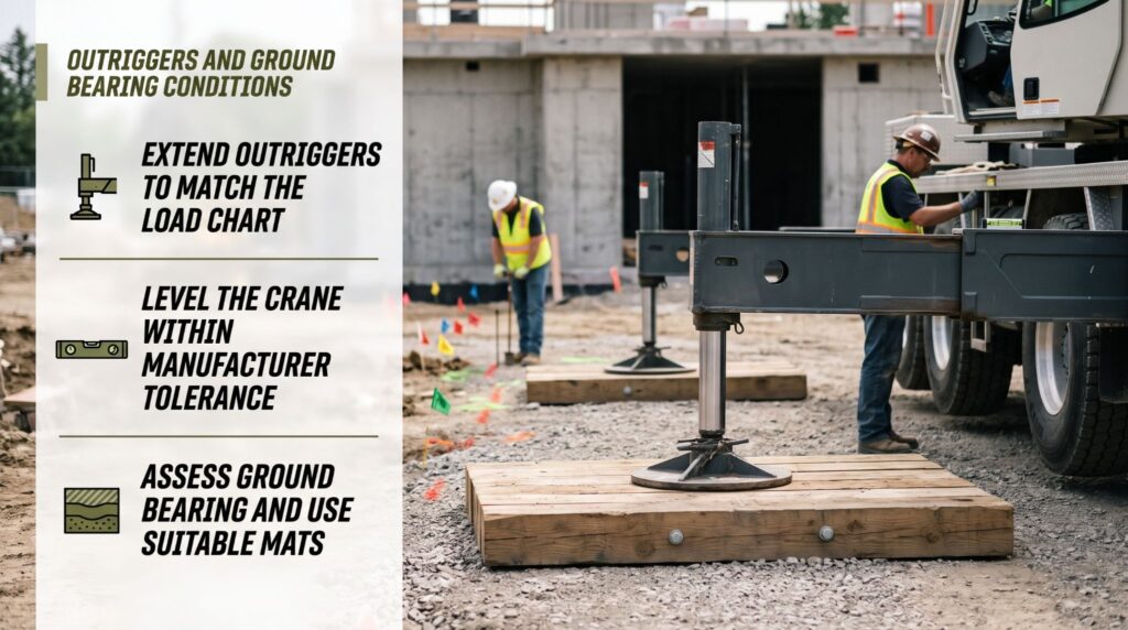
Counterweights resist overturning, but outriggers and the ground transfer the crane’s weight and load forces safely into the earth. If that support fails, the crane can tip regardless of how correctly its counterweight is configured. Outrigger setup and ground assessment are therefore as important as any figure on the load chart.
Outrigger extension directly affects capacity. Most load charts assume a specific outrigger position, often fully extended, and provide separate tables for intermediate or retracted positions where the crane allows them. Using the full-extension chart when the outriggers are only partially extended overstates the crane’s capacity. Some cranes use variable outrigger monitoring systems that adjust capacities automatically, but operators must still confirm that the system reflects the actual setup.
The crane must also be level within the manufacturer’s tolerance. Even a small out-of-level condition shifts the load radius as the crane slews and can reduce stability significantly at long radius. Lower the outriggers until the tires are clear of the ground where the manufacturer requires it, and check the level indicator before lifting and periodically during the operation.
Ground bearing capacity often decides whether a lift can proceed safely. Outrigger loads can be extremely high when the crane lifts near its rated limits, and they concentrate through relatively small float pads. Soft or saturated soil, recent backfill, buried utilities, voids, septic systems, basements, and underground vaults can collapse under that pressure. Assess the ground before setup, compare expected outrigger loads with the ground’s allowable bearing capacity, and use properly sized crane mats or engineered support systems to spread the load. On uncertain sites, obtain a qualified engineering assessment before the crane is positioned.
Key takeaway: Fully extend outriggers as the load chart requires, level the crane within manufacturer tolerance, assess ground bearing capacity, and use suitable mats or engineered supports, because ground failure can tip a crane even when the counterweight is correct.
Wind, Boom Radius, and Load Movement
Load charts describe capacity under defined conditions, usually with a freely suspended load, controlled movement, and wind within specified limits. Real lifts often introduce additional forces that the chart does not account for. Counterweight cannot remove the effects of wind or uncontrolled load movement.
Wind acts on both the boom and the load. Large, flat loads such as wall panels, roof trusses, glass units, and formwork can behave like sails, catching wind and pushing the load sideways. That side loading stresses the boom and can effectively increase the working radius as the load drifts away from the crane. Wind speed also tends to increase with height, so conditions at the boom tip may be much stronger than conditions at ground level. Follow the manufacturer’s wind limits, account for the load’s surface area, and monitor wind speed throughout the lift.
Boom extension and working radius affect permitted capacity at every stage of a lift. Booming down or telescoping out while holding a load increases load moment immediately. Plan the lift so the load stays within the radius allowed by the chart from pickup to placement, including the farthest point it will travel.
Load movement introduces dynamic loading. Sudden starts and stops, rapid slewing, abrupt hoist braking, and a swinging load can all create forces well above the static weight of the load. Use smooth, controlled inputs, attach tag lines where appropriate to manage rotation, and use rigging suited to the load’s weight, center of gravity, and shape. Stop the lift whenever wind, visibility, or load behavior exceeds the approved operating limits.
Key takeaway: Wind, boom radius changes, and dynamic load movement add forces beyond a load chart’s assumptions, so follow wind limits, keep the load within its permitted radius throughout the lift, operate smoothly, and stop when conditions exceed approved limits.
Conclusion
Counterweight configuration is a critical part of mobile crane stability, but safe lifting depends on the complete crane system and its working environment, as a counterweight balances the overturning effect of a suspended load only within manufacturer-engineered configurations and can never compensate for exceeding rated capacity, load moment rises with working radius even when load weight stays the same so the load chart and capacity limiter must match the exact setup, only manufacturer-approved counterweight arrangements installed by trained and authorized personnel may be used because unapproved changes can reduce forward stability or create backward tipping risk, correct outrigger extension, leveling, ground bearing assessment, and properly sized mats keep the crane supported, wind, boom radius changes, and dynamic load movement add forces that counterweight cannot remove, and thorough lift planning ties every element together, so before your next lift, confirm the load weight and rigging, verify the radius and boom configuration, check the counterweight and limiter settings against the correct load chart, assess the ground and set the outriggers as specified, review wind limits, and brief your crew and signal person so every pick on your site rests on verified data rather than assumption.
Frequently Asked Questions
Why do mobile cranes use counterweights?
Counterweights help balance the overturning effect of a suspended load. They allow the crane to achieve its rated lifting performance within the configurations specified by the manufacturer. Each approved counterweight arrangement corresponds to its own set of load chart capacities.
Does adding more counterweight always increase lifting capacity?
No. Only manufacturer-approved configurations may be used. Unapproved counterweights can invalidate the load chart, exceed structural limits, and create backward tipping risk when the boom is raised with little or no load. Never add improvised weight to a crane.
Can a crane tip over even with the correct counterweight?
Yes. Poor ground conditions, incorrect outrigger setup, an out-of-level crane, excessive load radius, wind, dynamic loading, and operation beyond rated limits can all cause instability. Counterweight is only one part of the crane’s overall stability.
What should be checked before a mobile crane lift?
Verify the load weight including rigging, working radius, boom setup, counterweight configuration, and rated capacity limiter settings. Confirm outrigger extension, leveling, ground support, and wind conditions. Use the correct load chart for the exact configuration, and establish clear communication with a qualified signal person where required.