Currently Empty: $0.00
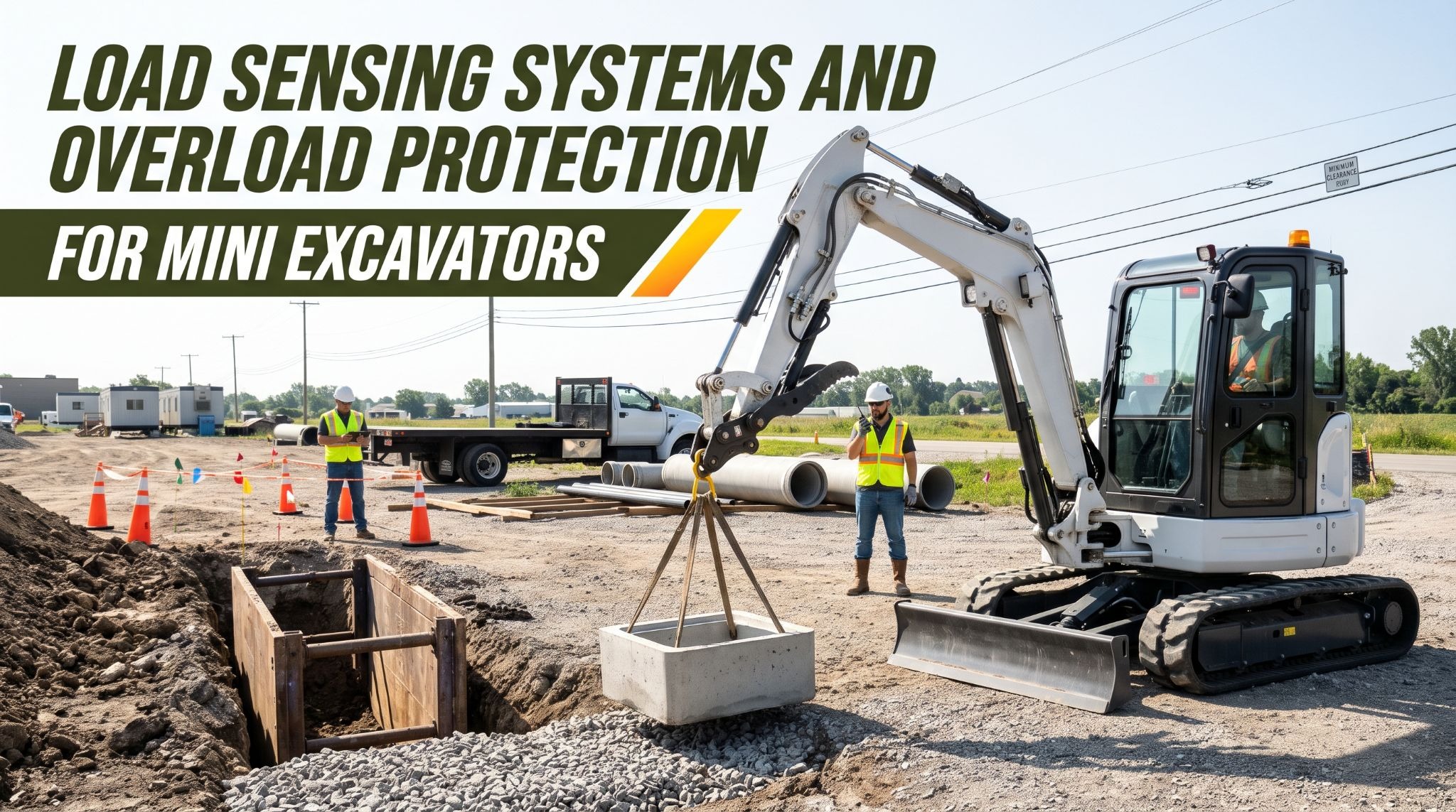
Load Sensing Systems and Overload Protection for Mini Excavators
A mini excavator’s hydraulic system does a great deal of work in a small space. One pump supplies the boom, arm, bucket, swing, travel motors, dozer blade, and often an auxiliary circuit for a breaker, auger, or thumb. During a typical cycle, the operator may curl the bucket, pull in the arm, raise the boom, and swing toward a truck in one smooth motion. How well the hydraulic system shares and controls that power affects how precisely the machine digs, how efficiently it uses fuel, and how predictably it handles a load.
Lifting adds a second layer of concern. Mini excavators often place pipes, set drainage structures, move retaining wall blocks, and lower manholes or catch basins. A compact machine has a narrow track gauge and a small counterweight, so its stability margin can disappear quickly as a load moves away from the tracks. Overload protection features are designed to warn the operator before a lift exceeds the machine’s limits. They work only when they are fitted, maintained, and understood.
For buyers comparing models, specification sheets can make these systems hard to evaluate. “Load sensing” describes a hydraulic control approach, not a guarantee of performance. “Overload warning” may describe a simple alarm on one machine and a more complete monitoring system on another. Some machines have neither.
Understanding How Hydraulic Load Sensing Works
Every hydraulic function on a mini excavator needs two things: flow to move the cylinder or motor at the desired speed, and enough pressure to overcome the load acting on it. Older and simpler hydraulic designs often use a fixed-displacement pump that delivers a set volume of oil at a given engine speed, whether or not the operator is moving a lever. Oil the machine doesn’t need returns to the tank, and the energy used to pump it is largely lost as heat.
A load sensing system takes a different approach. It typically uses a variable-displacement pump, often an axial piston design, with a control that adjusts pump output according to demand. Small signal lines carry pressure information from each working function back to the pump control. Shuttle or check valves select the highest load pressure among the active functions and send that signal to the pump. The pump then supplies only the flow required, at a pressure set a fixed margin above the highest working load. That margin, sometimes called the standby or margin pressure, gives the control valves enough pressure difference to meter oil accurately.
The practical result is that the pump works harder only when the job demands it. When the controls are in neutral, the pump drops to a low standby condition. When the operator feathers a lever to grade a footing or set a pipe, flow follows the lever position closely rather than surging. This helps reduce wasted hydraulic power and heat, and it often gives finer control at low speeds. Engine size and horsepower also matter, because the engine must provide enough power to support hydraulic pump demand while maintaining consistent machine performance under load. An undersized engine may struggle when multiple hydraulic functions operate simultaneously, while a properly matched engine and pump help deliver smoother operation and better efficiency. Many machines pair load sensing with electronic engine management or work modes that adjust engine speed to match hydraulic demand.
Load sensing isn’t a single specification that guarantees a better machine. Actual performance depends on pump size and design, control valve quality, engine output, system calibration, and hydraulic cooling capacity. A well-matched open-center system can perform well for many tasks, while a poorly matched load sensing system may disappoint. Treat load sensing as one feature to evaluate, then confirm how the machine actually feels in a hands-on demonstration.
Key takeaway: Load sensing systems adjust pump output to match the highest working demand, which can improve control and efficiency, but real performance depends on the complete hydraulic design and should be confirmed through a demonstration.
Managing Hydraulic Flow During Combined Operations
Productive excavator work depends on combining functions. A trenching pass blends arm-in and bucket curl. Loading a truck combines boom raise with swing. Fine grading may use boom, arm, and bucket together to hold a flat cutting path. The hydraulic system must divide available flow among these movements so each responds as the operator expects.
Problems appear when several functions demand more oil than the pump can supply at once. In a simple system, oil naturally flows toward the path of least resistance. A lightly loaded function, such as swing or bucket dump, may race while a heavily loaded function, such as boom raise with a full bucket, slows or stops. Operators feel this as jerky, unpredictable movement and compensate by constantly adjusting the levers, which slows the cycle and reduces precision.
Load sensing systems often address this with pressure-compensated or flow-sharing control valves. Pressure compensators help each function receive flow in proportion to its lever position, regardless of the load on it. Flow-sharing designs go a step further. When total demand exceeds pump capacity, they reduce flow to all active functions proportionally instead of starving the most heavily loaded one. The machine slows evenly, but every movement keeps its intended relationship. For tasks such as grading, placing pipe, or working beside a foundation, that consistency is often more valuable than raw speed.
Other features shape combined operation as well. Regeneration circuits reroute returning oil to speed certain movements, such as arm-in. Dedicated swing priority, travel straight valves, and separate pump sections can keep travel or swing steady while other functions run. Auxiliary circuits for attachments also draw from the same system, so a breaker or auger running at full flow leaves less available for other movements.
When comparing machines, ask the dealer how the hydraulic system handles combined functions, then test it. Dig a trench, load a truck, and grade a short section with a loaded bucket. Watch whether movements blend smoothly, whether one function stalls while another races, and whether the engine holds speed under load.
Key takeaway: Flow management determines how smoothly functions work together when demand exceeds pump capacity, so evaluate combined-function behavior through real digging, swinging, and grading tasks rather than relying on specifications alone.
Considering Load Weight and Working Position
The weight a mini excavator can safely lift isn’t a single number. It changes with the distance of the load from the machine, the height of the lift point, the direction of the upper structure relative to the tracks, the position of the dozer blade, and the attachment in use. That’s why manufacturers publish lift charts rather than a single lifting capacity.
A mini excavator balances over its tracks like a lever. The counterweight and upper structure hold the machine down, while the load at the end of the arm works against them. The farther out the load sits, the greater its leverage. A load that the machine handles comfortably close to the tracks can exceed its limits once the arm extends. Swinging also matters. Many machines are more stable lifting over the front with the blade down than lifting over the side, where the narrower track width provides less support.
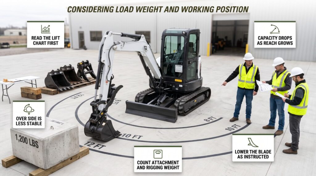
Lift charts reflect these differences. They typically list rated loads at set lift point heights and radii, often in separate columns for over front and over side, and for blade up and blade down. Under ISO 10567, rated lift capacity is commonly limited to the lesser of 75 percent of tipping load or 87 percent of hydraulic lift capacity. Charts usually specify the attachment and bucket fitted, and the conditions required, such as firm, level ground. Read the notes beneath the chart, because they define when its numbers are valid.
Account for everything hanging from the lift point. Lift chart values often assume a specific bucket or a defined lift point, and the weight of a heavier bucket, quick coupler, thumb, or rigging may need to be subtracted from available capacity. Know the real weight of the load from delivery tickets, product markings, or manufacturer data. Precast concrete structures, wet timber, and pipe filled with water or soil can weigh much more than expected.
Consider a crew setting a precast catch basin beside a new parking lot. The basin sits on the delivery truck about 10 feet from the excavator’s swing center, but the placement point is 14 feet away over the side. A capacity that works at the truck may not work at the placement point. The safe answer is to check the chart for the entire path, then reposition the machine closer or place the basin over the front with the blade down.
Key takeaway: Safe lifting capacity changes with radius, height, swing direction, blade position, and attachment weight, so check the manufacturer’s lift chart for the full path of every lift and count the attachment and rigging against capacity.
Checking Stability and Ground Conditions
Hydraulic systems, however advanced, can’t eliminate the risk of tipping or loss of stability. Lift charts and overload warnings assume the machine sits on firm, level ground. Real jobsites rarely offer that everywhere. Soft fill, recent backfill, wet clay, slopes, and ground near excavation edges can all reduce the stability margin before the load even rises.
Walk the work area before any lift. Look for soft spots, voids, loose material, buried utilities, septic systems, and recently backfilled trenches. Keep the machine well back from the edges of excavations and trenches, since the concentrated weight of a loaded mini excavator can collapse an unsupported wall. Position the machine on the firmest, most level surface available, and level the working pad if needed before beginning lifting work.
Use the dozer blade as the manufacturer instructs. On many mini excavators, lowering the blade to the ground increases stability when lifting over that end of the machine, which is why lift charts often show higher values for blade down over front. The blade only helps when it rests firmly on stable ground. Where machines are equipped with additional stabilizing features, deploy them according to the operator’s manual.
Operating technique protects stability as much as setup. Lift and swing with smooth, controlled movements, since sudden starts and stops create dynamic forces that can push the machine past its limits. Keep suspended loads low, and avoid swinging a load quickly or traveling with it unless the manufacturer permits that operation and conditions are suitable. On slopes, follow the manufacturer’s guidance on machine orientation and avoid swinging a load toward the downhill side. Wear the seat belt throughout operation.
Keep people clear of the lifting zone at all times. No one should stand beneath a raised load or within the swing radius. Use a qualified signal person when the operator can’t see the load or landing point clearly, and agree on hand signals or radio procedures before the lift begins. Rigging should be rated for the load, attached only to approved lifting points, and inspected before use. Check overhead for power lines and maintain the required clearance distances.
Never rely on a hydraulic warning system as a substitute for proper load assessment. An alarm that hasn’t sounded doesn’t mean a lift is safe.
Key takeaway: Hydraulic systems can’t prevent tipping on poor ground, so assess the surface before lifting, keep the machine back from edges, use the blade as instructed, move loads smoothly, and keep everyone clear of the lifting zone.
Inspecting Sensors, Valves, and Hydraulic Components
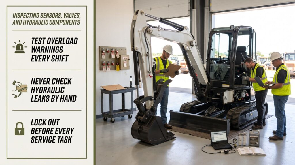
Load sensing and overload protection systems depend on components that wear, loosen, and drift out of calibration over time. A small signal line that leaks, a sensor connector packed with mud, or a sticking valve can change how the machine responds or prevent a warning from sounding. Routine inspection keeps these systems working as intended.
During the daily walk-around, inspect hydraulic hoses and fittings for leaks, abrasion, kinks, and damage, paying attention to hoses that flex through the boom swing and arm movement. Check the small-diameter load sensing signal lines as carefully as the main hoses, since a damaged signal line can affect pump response. Look at overload sensors, wiring harnesses, and electrical connectors for damage, corrosion, and loose fittings. Confirm that hose burst valves on the boom and arm cylinders are present and undamaged. With the machine started, test the overload warning light and alarm according to the manufacturer’s procedure.
Never use your hand to search for a hydraulic leak. Fluid escaping through a pinhole under high pressure can penetrate skin and cause an injection injury that requires immediate emergency medical treatment, even when the wound looks minor. Use a piece of cardboard or wood, and wear gloves and eye protection. If anyone is struck by escaping fluid, seek emergency care at once and tell medical staff it is a hydraulic injection injury.
Hydraulic oil and filtration protect every valve and sensor in the system. Use the oil type and viscosity specified by the manufacturer, check the level with the machine positioned as the manual instructs, and keep fill points clean. Replace hydraulic filters and the tank breather on schedule. Contamination can cause compensators and control valves to stick, which affects load sensing response and flow sharing.
Watch for warning signs during operation. Slow or uneven movement, functions that stall under combined demand, a pump that whines or hunts, rising oil temperature, a boom that drifts under load, or warning lights that appear without explanation all need investigation. Don’t keep working through a suspected fault, especially one that affects the machine’s ability to hold or warn about a load.
Before any service, lower the boom, arm, bucket, and blade fully to the ground. Shut down the engine, remove the key, apply your site’s lockout procedure, and relieve hydraulic pressure according to the manufacturer’s instructions. Never work beneath a raised boom held only by hydraulics. Pump margin settings, relief valve adjustments, sensor calibration, and valve repairs should be handled by qualified technicians using the manufacturer’s procedures and test equipment. Never raise relief settings or adjust overload thresholds to gain capacity.
Key takeaway: Inspect hoses, signal lines, sensors, connectors, and hose burst valves regularly, test warning systems every shift, never check leaks by hand, lock out before service, and leave calibration and valve adjustments to qualified technicians.
Conclusion
Load sensing systems help a mini excavator match hydraulic output to demand, improving control and efficiency when they’re well designed and properly matched. Flow management determines how smoothly functions combine during digging, swinging, and grading. Overload protection adds an important layer of warning during lifting, but features vary widely by model and don’t replace knowledge of the load. Safe lifting still depends on the lift chart, the real weight of the load and attachment, the working position, and firm, stable ground. Regular inspection of sensors, valves, signal lines, and hydraulic components keeps these systems reliable over the machine’s working life.
Frequently Asked Questions
What does a load sensing system do on a mini excavator?
A load sensing system monitors the pressure demand of the active hydraulic functions and adjusts pump output to match. Signal lines send the highest working pressure back to a variable-displacement pump, which supplies the required flow at a set margin above that pressure. This reduces wasted hydraulic power when demand is low and supports finer control at low speeds. Actual performance depends on pump design, control valves, engine output, and system calibration.
Does every mini excavator have overload protection?
No. Overload warning devices and lifting restrictions vary by manufacturer and model. Some machines include them as standard, others offer them as options, and some have none. Hose burst protection valves on the boom and arm cylinders also vary. If you plan to lift pipe, structures, or materials, verify the exact equipment fitted to the specific machine and check the requirements that apply in your region and application.
Can overload protection prevent every lifting accident?
No. Most overload systems measure hydraulic conditions at a given moment and may not account for slopes, soft ground, dynamic loads from swinging, or unrated rigging. Operators must still know the real load weight, read the lift chart for the full path of the lift, set up on firm, level ground, and keep people clear of the lifting zone. Treat the warning system as a backup, never as a substitute for planning.
Why does machine position affect lifting capacity?
A mini excavator balances over its tracks, and a load’s leverage increases as it moves farther from the machine. Lifting over the side usually provides less stability than lifting over the front, and lowering the dozer blade often increases capacity over that end. Lift point height, attachment weight, and ground conditions also affect the permitted load. That’s why manufacturers publish lift charts with values for different radii, heights, and machine configurations.